
The following is an account of the interfacing of my HomeVision to my central heating controller by Keith Doxey. Keith’s DIY Home Automation website can be found here www.diyha.co.uk. Also check out our Heating Control Forums Here.
|
|
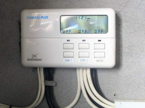
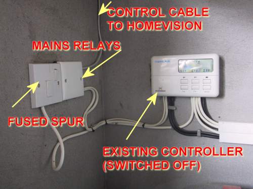
| Existing Controller The existing heating controller is a 3 channel affair – Upstairs, Downstairs and Hot water. We will only require an interface to channels 1 and 2 as our hot water is supplied from the stove and not the central heating boiler. We are happy enough to use the existing thermostats – downstairs there are 6 zones of under-floor heating with a stat in each zone controlled by motorised valves on the manifold. Upstairs the radiators all have TRVs.Although we are using a dedicated hardware controller (HomeVision – which has proved utterly reliable since it was installed in July 1997), we also wanted to leave the existing heating timer connected so it is possible to easily use it again if the need arises. |
|
|
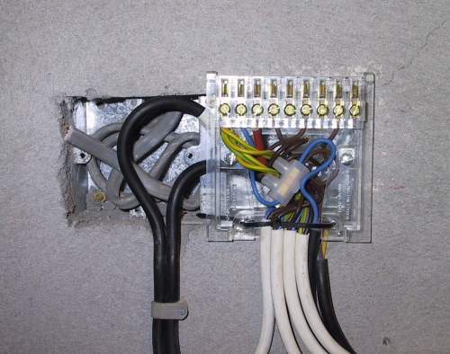
| Interface The existing controller was removed (eventually – long story). I had the manual for the controller and we were able to easily locate the terminals we needed to connect to. WARNING – Do not mess with mains voltages. If you are unsure ask a qualified electrician to do the work! |
|
|
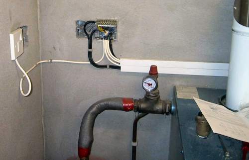
| Housing We were lucky because there was a spare wall box beside the fused spur supplying the mains. We decided to use this space to house the mains relays rather than buying and fixing another housing to the wall. |
|
|
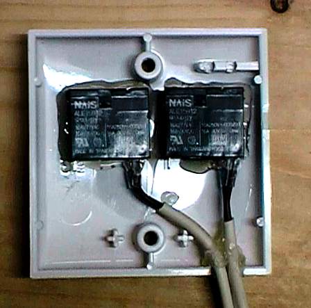
| Mains Relays The mains relays were attached to the back of a Clipsal single gang blanking plate using a hot glue gun. All connections were soldered and insulated using heat shrink sleeving. The relays are from Maplins. |
|
Heating Circuit – Click for Ful Size Version |

Keith’s Circuit Diagram & Explanation
The switch mounted LED’s are fed from the 12 volt supply via resistors R1 (Downstairs Zone) and R2 (Upstairs Zone). HomeVision pulls Port A3/A4 low when the heating is OFF which short the LED side of the resistor to ground, this extinguishes the LEDs.
The relays are fed from the 12 volt supply and are grounded by Port A1/A2 going low to operate the relay. This turns the heating ON. The mains side of the relays are wired in parallel to the existing programmer contacts and the programmer is set to OFF. In the event of HomeVision or Relay failure the existing programmer can be switched on and conventional heating control is instantly available.
As the relays are connected to 240V AC is important that all connections are insulated using heat shrink sleeving and the enclosure containing the relays is only accessible by means of a screwdriver.
|
|
| FinishedThe “clever stuff” can now all be done in software. HomeVision could, for example, automatically shut off the heating if we arm the alarm. I also have a “fail-safe” scheduled event set for 2:00am that turns off the heating to both floors in case it has somehow been left on. |
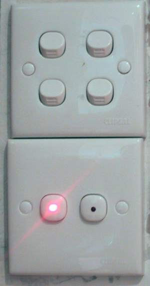 |
Control Keith manufactured two sets of these “LED Switches”. One set for the kitchen (pictured) and another set for the Master Bedroom. They were made using Clipsal momentary contact switches and inserting an LED into their tip. Although these are mains rated they are connected to low voltage circuits back to HomeVision via CAT5. One circuit informs HomeVision that the switch has been pushed while a second circuit controls the LED. |
Before we had this setup I used to have to go to the garage to give the heating a boost outside of the programmed times. Now it’s simply a matter of hitting the button. One of the great things about the switches is the visual aspect of knowing at a glance what heating is on and where.
A press of the left button brings on the downstairs heating for a 2 hour period…
INPUT PORT ‘LOW’ EVENT # 0 ‘Downstairs Heating Switch’
If
Flag #6 (Downstairs Heating ON) is set
Then
Do macro #12 (Downstairs Heating OFF) once
Stop and clear timer #15 (Downstairs Heating Timer)
Else
Do macro #11 (Downstairs Heating ON) once
Load timer #15 (Downstairs Heating Timer) with 2:00:00.00 and start
End If
MACRO EVENT # 11 ‘Downstairs Heating ON’
Set output port A-1 (Downstairs Heating Relay) high
Set output port A-3 (Downstairs Heating LED) low
Set flag #6 (Downstairs Heating ON)
MACRO EVENT # 12 ‘Downstairs Heating OFF’
Set output port A-1 (Downstairs Heating Relay) low
Set output port A-3 (Downstairs Heating LED) high
Clear flag #6 (Downstairs Heating ON)
While pressing the right hand button brings on the upstairs for 1 hour…
INPUT PORT ‘LOW’ EVENT # 1 ‘Upstairs Heating Switch’
If
Flag #7 (Upstairs Heating ON) is set
Then
Do macro #14 (Upstairs Heating OFF) once
Stop and clear timer #16 (Upstairs Heating Timer)
Else
Do macro #13 (Upstairs Heating ON) once
Load timer #16 (Upstairs Heating Timer) with 1:00:00.00 and start
End If
MACRO EVENT # 13 ‘Upstairs Heating ON’
Set output port A-2 (Upstairs Heating Relay) high
Set output port A-4 (Upstairs Heating LED) low
Set flag #7 (Upstairs Heating ON)
MACRO EVENT # 14 ‘Upstairs Heating OFF’
Set output port A-2 (Upstairs Heating Relay) low
Set output port A-4 (Upstairs Heating LED) high
Clear flag #7 (Upstairs Heating ON)
As the heating physically connect to HomeVision it’s also possible to turn the heating on and off with a variety of methods other than the switches. For example, IR Remote, HomeVision TV Menus, any X10 transmitter, Phone either internally or dialling into the house from anywhere in the world.
The Future
 The new method I’m thinking of would allow you to enter various times. I’ve been toying with the idea of trying to program HomeVision to accept multiple presses of the switches to allow X number of “periods” to be easily added to the timer. I would setup a single press of each button to start a 30 minutes timer. Each subsequent press would add an additional 30 minutes to the time. For example, if you pressed the button 3 times you would have set the heating to come on for an hour and a half. I also thought of flashing the LEDs (simulation shown) to indicate how many “periods” were remaining.
Another feature I’d like to add in the future is a weather compensator. This monitors the outside temperature and brings the heat on early on a particularly cold day (for example). We were offered one of these at build time for around £1,000 but we should be able to add this feature with an inexpensive temperature probe and some more HomeVision programming.
Many thanks to Keith Doxey as ever for all his hard work!!
Click here to see HV Pictures & Description
Click Here for Custom Solution’s official page on the “International Version” of HomeVision.
Disclaimer.
Whilst the information provided here should assist you in interfacing to your heating system, it will not necessarily apply in total or in part. There are many different types and configurations of heating system, and advice should be sought on your particular configuration before attempting to interface. Not all types of system will necessarily be open to interfacing, perhaps having in-built or proprietary controllers.
Things to consider include: gravity or fully-pumped, controller contact voltage (ie. 230v, 24v, 12v), use of motorised valves (on some configurations you must not fire a boiler without FIRST ensuring a valve is open – indeed the correct wiring of these valves enforces this rule in most instances), cylinder and room thermostats, combination boilers with integral pumps. This list is not exhaustive, and serves as a pointer for things to consider. At the end of the day, if you have a good understanding of how the system works, apply common sense and check everything you should not have any problems.
Be the first to comment on "HomeVision Central Heating"